Here, We provide BEE GTU Paper Solution Winter 2021. Read the Full Basic Electrical Engineering gtu paper solution given below.
BEE GTU Old Paper Winter 2021 [Marks : 70] : Click Here
(a) Calculate current, resistance and energy consumed by an oven rated 230V,
1KW when used for 20 hours. Also calculate the electricity bill at the rate
of Rs. 7/- per unit.
To calculate the current, resistance, and energy consumed by the oven:
- Current (I) = Power (P) / Voltage (V) = 1000W / 230V = 4.35A
- Resistance (R) = Voltage (V) / Current (I) = 230V / 4.35A = 52.91Ω
- Energy consumed (E) = Power (P) * Time (t) = 1000W * 20 hours = 20,000 Wh
To calculate the electricity bill:
- Total energy consumed (E) = 20,000 Wh
- Total number of units (U) = Energy (E) / 1000 = 20,000 / 1000 = 20 units
- Total bill (B) = Total units (U) * Rate per unit (R) = 20 * 7 = 140 Rs
So, the electricity bill for 20 hours of usage at the rate of Rs. 7/- per unit would be 140 Rs.
(b) Define Power Factor. What are the disadvantages of Low Power Factor?
Power Factor is the measurement of how incoming power is being effectively used in electrical power system.
Disadvantages for Low Power Factor
- Large kVA rating for equipment
- Greater conductor size
- large copper losses
- poor voltage reulation
- the reduce handling capacity of the system
(c) Summarize; Mathematical & Waveform representation of an alternating
sinusoidal quantity (voltage or current). Demonstrate time period, peak
value, Peak to Peak value, Average value, RMS value. Write definition of
all.
(a) Write statement of Superposition, Norton and Thevenin theorem.
The superposition theorem states that in any linear network containing two or more
sources, the current in any element is equal to the algebraic sum of the current caused
by individual sources acting alone, while the other sources are inoperative.
Norton’s Theorem states that “Any linear circuit containing several energy sources and
resistances can be replaced by a single Constant Current generator in parallel with a
Single Resistor“.
Thevenin’s Theorem states that “Any linear circuit containing several voltages and
resistances can be replaced by just one single voltage in series with a single resistance connected across the load”.
(b) Write classification of Electric Networks.
Electric networks can be classified into several categories based on various criteria, including the type of components, the topology of the network, and the type of analysis performed. Some common classifications are:
- Passive vs. Active networks: Passive networks are composed of passive components like resistors, capacitors, and inductors. Active networks contain active components like transistors, diodes, and operational amplifiers that can amplify the signal.
- Linear vs. Non-linear networks: Linear networks are characterized by a linear relationship between the input and output signals, while non-linear networks exhibit a non-linear relationship.
- Time-invariant vs. Time-variant networks: Time-invariant networks have a constant response over time, while time-variant networks have a response that changes with time.
- Continuous-time vs. Discrete-time networks: Continuous-time networks use continuous-time signals, while discrete-time networks use sampled signals.
- Series vs. Parallel networks: Series networks are composed of components connected in a series, meaning that the same current flows through each component. Parallel networks are composed of components connected in parallel, meaning that the same voltage appears across each component.
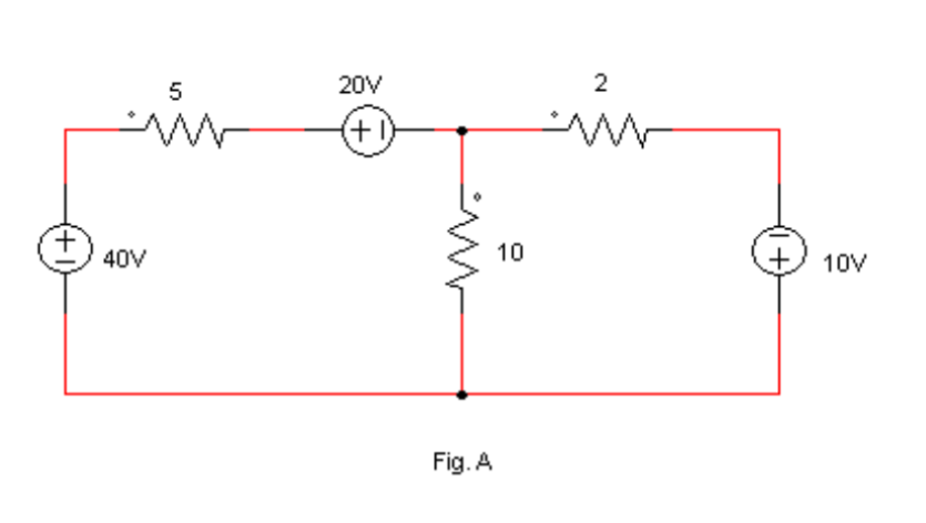
(c) Write applications of Thevenin’s theorem. Find the current passing
through 2 Ω (Fig. A) resistance using Thevenin’s theorem. All resistances
are in Ω.
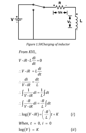
[OR] (c) Derive the expression for the rise of current in R-L series circuit when a
D.C. supply is switched on to it. Define time constant of it.
(a) Define Form factor. State the value of form factor for Sinusoidal
waveform.
Form factor is a term used in electrical engineering to describe the shape of a waveform, specifically the relationship between its average value and its peak value. It is a dimensionless quantity and is used to compare the waveform shapes of different signals.
The form factor of a sinusoidal waveform is defined as the ratio of the root-mean-square (RMS) value to the peak value:
Form factor (Kf) = RMS value / Peak value = √(2) / 2 = 0.707
The form factor of a sinusoidal waveform is a constant value and is equal to 0.707. This value is important in electrical engineering, as it is used to calculate the effective power in AC systems and to determine the required size of electrical components such as transformers and inductors.
(b) A series resonance network consisting of a resistor of 30Ω, a capacitor of
2μF and an inductor of 20mH is connected across a sinusoidal supply
voltage which has a constant output of 9 volts at all frequencies. Calculate,
the resonant frequency, the current at resonance, the voltage across the
inductor and capacitor at resonance, the Quality factor and the bandwidth
of the circuit.
Given: Resistor = 30 Ω Capacitor = 2 μF = 2 × 10^-6 F Inductor = 20 mH = 20 × 10^-3 H Voltage supply = 9 V
The resonant frequency of the circuit can be calculated using the following equation:
f_res = 1 / (2π √(L * C))
where L is the inductance and C is the capacitance. Substituting the values, we get:
f_res = 1 / (2π √(20 × 10^-3 * 2 × 10^-6)) = 1591 Hz
At resonance, the impedance of the circuit is at a minimum and the current through the circuit is at a maximum. The current at resonance can be calculated using the following equation:
I_res = V / Z_min = V / R
where Z_min is the minimum impedance and R is the resistance of the circuit. Substituting the values, we get:
I_res = 9 / 30 = 0.3 A
The voltage across the inductor and capacitor at resonance can be calculated using the following equation:
V_L = I_res * X_L = I_res * 2π * f_res * L V_C = I_res * X_C = I_res * 1 / (2π * f_res * C)
where X_L and X_C are the reactances of the inductor and capacitor, respectively. Substituting the values, we get:
V_L = 0.3 * 2π * 1591 * 20 × 10^-3 = 11.4 V V_C = 0.3 * 1 / (2π * 1591 * 2 × 10^-6) = 11.4 V
The quality factor of the circuit, also known as the Q-factor, is a measure of the resonant circuit’s damping and is defined as the ratio of energy stored in the circuit to energy lost per cycle. It can be calculated using the following equation:
Q = X_L / R = 2π * f_res * L / R
Substituting the values, we get:
Q = 2π * 1591 * 20 × 10^-3 / 30 = 20.4
The bandwidth of the circuit is defined as the range of frequencies over which the circuit exhibits resonance and can be calculated using the following equation:
Bandwidth = f_res / Q = 1591 / 20.4 = 78.1 Hz
(c) With the help of waveforms and phasor diagrams, comment on phase
relationship between voltage and current in single phase RLC series
circuit.
OR
(a) Define Q-factor of RLC series circuit. What is the importance of it?
The Q-factor of an RLC series circuit is a dimensionless quantity that describes the damping of the circuit’s resonant response. It is defined as the ratio of the energy stored in the circuit to the energy lost per cycle due to resistance.
Q-factor = Energy stored in the circuit / Energy lost per cycle = X_L / R (where X_L is the reactance of the inductor)
The importance of the Q-factor in an RLC series circuit is that
it determines the circuit’s ability to store energy and its efficiency in resonant energy transfer. A higher Q-factor indicates that the circuit is more resonant and has a sharper frequency response, which can result in improved signal processing and filtering. A lower Q-factor, on the other hand, indicates that the circuit is less resonant and has a broader frequency response, which can result in improved stability and reduced susceptibility to external disturbances.
The Q-factor also determines the bandwidth of the circuit, which is the range of frequencies over which the circuit exhibits resonance. A higher Q-factor results in a narrower bandwidth, while a lower Q-factor results in a broader bandwidth.
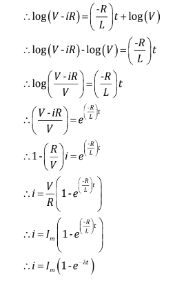
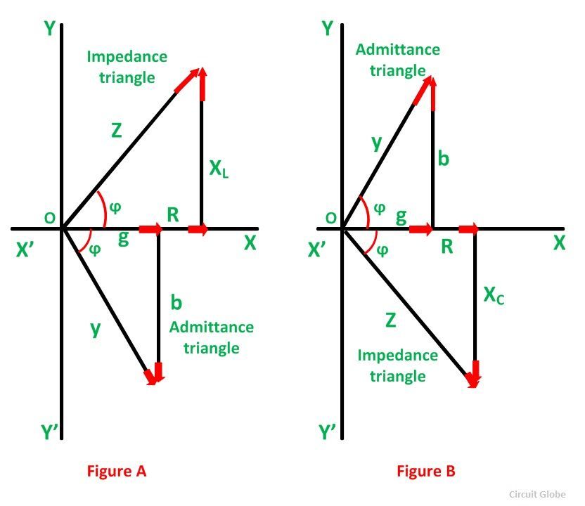
(b) Draw Impedance triangle and Admittance triangle.
(c) A balanced 3-phase load consists of 3 coils each of resistance of 6 Ω and
inductive reactance of 8 Ω. Determine line current and power absorbed
when the coils are 1. Star connected and 2. Delta connected across 400V,
3-phase supply.
Star connection:
The line voltage of a 3-phase, 400V system is equal to the phase voltage, which is given as: V_L = √(3) * V_phase = √(3) * 400V = 686.6V
The equivalent impedance of each coil in a star connection is given by: Z_eq = √(R^2 + X_L^2) = √(6^2 + 8^2) = √(100) = 10Ω
The line current for a star connected 3-phase load can be calculated as: I_L = V_L / Z_eq = 686.6V / 10Ω = 68.66A
The power absorbed by each coil can be calculated as: P = I_L^2 * R = 68.66A^2 * 6Ω = 2740.3W
So, the total power absorbed by the 3-phase load in star connection is: P_total = 3 * P = 3 * 2740.3W = 8220.9W
Delta connection:
The equivalent impedance of each coil in a delta connection can be calculated as: Z_eq = (R + jX_L) + (R + jX_L) + (R + jX_L) = 6Ω + j8Ω + 6Ω + j8Ω + 6Ω + j8Ω = 18Ω + j24Ω
The line current for a delta connected 3-phase load can be calculated as: I_L = V_L / Z_eq = 400V / (18Ω + j24Ω)
The power absorbed by each coil can be calculated as: P = V_L * I_L * cos(θ)
So, the total power absorbed by the 3-phase load in delta connection is: P_total = 3 * P = 3 * (V_L * I_L * cos(θ))
where θ is the phase angle between the voltage and current.
(a) State advantages of polyphase systems.
There are several advantages of polyphase systems over single phase systems, including:
- Increased power transfer capability
- Improved distribution efficiency
- Reduced voltage drop
- Reduced weight and size of equipment
- Improved reliability
- Improved power factor
(b) Mention Merits and Demerits of Induction Motor.
Merits of Induction Motors:
- Reliability
- Cost-effective
- High Efficiency
- Easy to control
- Easy maintenance
- Robustness
Demerits of Induction Motors:
- Limited starting torque
- Poor power factor
- Not suitable for high-speed applications
- Not suitable for frequent starting and stopping
(c) Explain construction of single phase Transformer.
A single-phase transformer is an electrical device that is used to transfer electrical energy from one circuit to another through electromagnetic induction.
It consists of two coils, known as the primary coil and the secondary coil, that are wound around a magnetic core. The core is typically made of a magnetic material, such as laminated iron or iron powder, to enhance the magnetic field.
The primary coil is connected to the input voltage source and the secondary coil is connected to the load. When an alternating current is applied to the primary coil, a magnetic field is created that induces a voltage in the secondary coil.
The voltage in the secondary coil is proportional to the number of turns in the secondary coil relative to the primary coil. This allows the transformer to either step up or step down the voltage depending on the ratio of turns between the primary and secondary coils.
The construction of a single-phase transformer typically includes the following components:
- Magnetic Core: This is the central component of the transformer, made of a magnetic material, such as laminated iron or iron powder.
- Primary and Secondary Coils: These are the two coils that are wound around the magnetic core. The primary coil is connected to the input voltage source, and the secondary coil is connected to the load.
- Insulation: This is used to electrically isolate the primary and secondary coils from each other and from the core.
- Terminals: These are used to connect the primary and secondary coils to the voltage source and the load.
- Case: This is used to enclose the magnetic core, coils, insulation, and terminals to protect the transformer from external damage and to prevent any electrical shock hazards.
OR
(a) Write applications of Auto Transformer.
Auto transformers are widely used in various applications due to their ability to provide high-efficiency voltage transformation with a compact design.
- Voltage regulation
- Load balancing:
- Motor starting
- Power factor correction
- High-voltage power distribution
- Audio and signal amplification
(b) Explain the principle of operation of an Alternator.
An alternator is an electrical generator that converts mechanical energy into electrical energy. The principle of operation of an alternator is based on Faraday’s law of electromagnetic induction. According to Faraday’s law, whenever a magnetic field cuts through a conductor, an electromotive force (EMF) is induced in the conductor, which generates an electric current.
In an alternator, a rotating magnetic field is created by the magnetic poles of a rotor, which rotates inside a stationary stator. The stator has three or more coils of wire, each wound around a core made of iron or other magnetic material. The stator coils are connected to an external circuit to form the load, while the rotor is connected to a prime mover, such as a steam turbine, gasoline engine, or wind turbine, that provides the rotational energy to turn the rotor.
As the rotor rotates, the magnetic field cuts through the stator coils, inducing an EMF in the stator coils and generating an alternating current (AC) in the load. The AC voltage produced by the alternator is regulated by a voltage regulator, which adjusts the amount of current flowing in the rotor coils to maintain a constant output voltage.
(c) Describe construction of a DC machine.
A DC machine is an electrical machine that converts mechanical energy into electrical energy or vice versa. The construction of a DC machine consists of several components, including the rotor (armature), stator, commutator, brushes, and field windings.
Rotor (Armature): The rotor is the rotating part of the DC machine and is also referred to as the armature. It consists of a cylindrical iron core, which is wound with a large number of insulated copper wire coils.
Stator: The stator is the stationary part of the DC machine and surrounds the rotor. It is made of a laminated iron core and houses the field windings.
Commutator: The commutator is a rotating part that is attached to the rotor and is responsible for reversing the current direction in the armature coils as they rotate.
Brushes: Brushes are spring-loaded carbon or graphite blocks that provide a conductive connection between the commutator and the external circuit. They rub against the commutator and transfer the electrical energy from the armature to the external circuit.
Field Windings: Field windings are located on the stator and are used to create a magnetic field. They are typically wound around the laminated iron core and can be made of either DC or AC current.
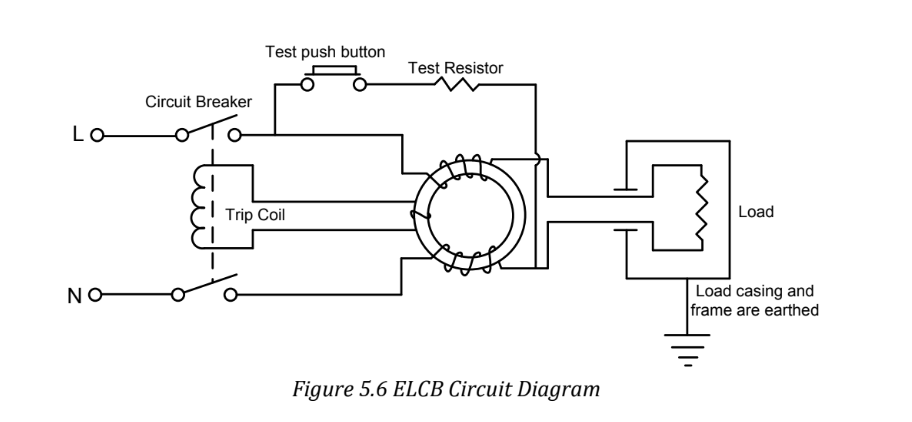
(a) Briefly explain block diagram of ELCB.
It is current operated device designed to operate when a leakage current exceeds the
predefined value.
It consists of a operating coil and a trip mechanism which operated the circuit when
required.
The coil is supplied through 1-Ф supply so current in phase & neutral wire will be same.
This current will produce flux linkages same in magnitude but of opposite direction. This
will result zero net flux in tripping coil of relay.
When fault or leakage current exceeds the limit higher current will flow in phase
conductor than neutral current.
Resultant flux now is out of balance in tripping coil of relay. Difference of flux will induce
emf in the coil which opens the contact of ELCB and isolate the circuit from the supply.
(b) Mention important points regarding Earthing of Electrical Installation.
“The earthing is the connection of general mass of earth to electrical apparatus in such a
manner as to ensure all time an immediate energy discharge without danger”.
The earth is made up of a material that is electrically conductive. A fault current will flow
to earth through the live conductor, provided it is earthed.
The Conventional system of Earthing is done by digging of a large pit into which a GI pipe or a Copper plate is positioned with the layers of charcoal and salt.
When system is without earthing and if short circuit occurs and human body touches the
metal part, current will get return path through human body.
When system is properly earthed and if short circuit occurs and human body touches the
metal part, current will not get path through human body. Because circuit is already
provided with low resistance path through earthing.
An effective earthing is made through any wire, pipe, rod or metal plate known as earth
electrode.
The connecting wire between electrical apparatus and earth electrode is known as
earthing lead or main earthing conductor.
Purpose of Earthing
- To avoid electric shock to human body.
- To avoid risk of fire due to earth leakage current through unwanted path.
- Ensure that all exposed conductive parts do not reach a dangerous potential
- Maintain the voltage at any part of an electrical system.
The qualities of a good Earthing
- Must be of low electrical resistance
- Must be of good corrosion resistance
- Must be able to dissipate high fault current repeatedly
(c) Write short technical notes on Battery Maintenance. What precautions to
be taken for Lead Acid Batteries?
Battery Maintence
Check the battery’s state of charge. Most batteries have a State of Charge Indicator on top of the battery that will give you an on the spot diagnosis of the battery condition.
Ensure the battery top is clean, dry, free of dirt and grime. A dirty battery can discharge across the grime on top of the battery casing.
Inspect the terminals, screws, clamps and cables for breakage, damage or loose connections. These should be clean, tight and free of corrosion.
Apply a thin coating of high temperature grease to posts and cable connections for added protection.
Inspect the battery case for obvious signs of physical damage or warpage. This usually indicates the battery has been overheated or has been overcharged.
If you have a maintainable battery, it is important to check if the battery has sufficient electrolyte covering the battery plates. If topping up is required, do not over fill as the fluid levels will rise when the battery is fully charged and may overflow. Top up using distilled or demineralised water and never fill with sulphuric acid.
Lead-Acid Battery Safety Precautions
Store or recharge lead-acid batteries in a well ventilated area away from sparks or open
flames.
Keep lead-acid batteries that are damaged in properly labeled, acid-resistant secondary
containment structures.
Wear acid-resistant goggles/face shield, gloves, and if available, an apron, when recharging or handling lead-acid batteries,
Keep lead-acid battery vent caps securely in place.
Flush eyes immediately with water for 15 minutes and then promptly seek medical attention if acid gets into your eye(s) Rinse the affected area immediately with large amounts of water if acid gets on your skin.
Seek medical attention if the chemical burn appears to be second degree or greater.
Never overcharge a lead-acid battery and only replenish fluid with distilled water.
Locate emergency eyewash stations close to lead-acid battery storage and charging areas.
Post “Flammable – No Smoking” signs in lead-acid storage and charging areas.
OR
(a) Mention advantages of MCB over Fuse.
MCB has several advantages over fuse:
MCB is more sensitive to current than the fuse. It detects any abnormality in the current flow and automatically switches off the electrical circuit.
In the case of MCB, the fault zone of the electrical circuit can be easily identified. Faulty circuit trips to the off position. On the other hand in case of the fuse, the complete fuse wire needs to be checked by opening fuse grip for confirming the fault zone.
With MCB it is very simple to resume to the supply. You just need to push the knob of MCB back to on position. But in case of the fuse, the entire fuse wire needs to be replaced.
MCB provides a better interface with the help of knob than a fuse. In case of the fuse, the compete for handle needs to be taken care out.
Handling MCB is electrically safer than handling a fuse.
MCB is reusable and hence has less maintenance and replacement cost. Whereas a fuse needs to be replaced whenever it goes faulty.
(b) Mention basic guidelines (Safety Rules) regarding safe handling of
electricity.
- Never touch/handle any electrical appliance with wet hands. A wet body can act as a good conductor of electricity. In the case of any leakage, the person with wet body/hands will get a severe shock.
- Never try to pull away from a person who has contacted a live wire. Electricity is a very convenient and useful form of energy. However, if proper precautions are not taken, electricity can be very hazardous Magnets and Magnetic Effect of Current.
- Wiring. All wires used in electrical circuits should be covered with a good insulator. So, always use good quality electrical wires.
- Joints in wires. All wires /electrical joints should be properly covered with insulation tape.
- Electrical connections. All electric connections at switches, plugs. sockets and junctions must be tight. Fuses and switches must be connected in the live wires.
- Repairs or replacement. Defective switches, sockets, or, wires should be replaced immediately. Whenever any repair or replacement of any electrical component is required, put on rubber gloves and rubber shoes, or stand on a dry wooden stand. Before starting repairs, the main switch should be switched off. The testers, screwdrivers, pincers, and other repairing tools should have proper insulation on them.
- Fuse. Each circuit should have a fuse of the proper rating. Fuses should be one should never try to pull away from a person who has contacted a live wire connected to the live wire.
- Earthing. All electrical appliances must be properly earthed. By proper earthing, the danger of any accidental shock can be reduced.
- Dealing with accidents. In case of any short-circuiting, or any accidental contact of a person with a live wire, do as follows: immediately switch off the main switch. provide him or her support of some non-conducting material such as rubber sheet, or wood.
(c) Explain construction of cable in detail with neat diagram. Label all the
parts.
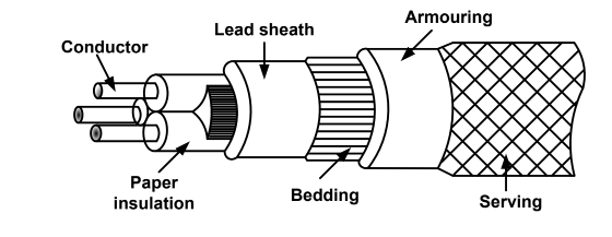
Conductor: Conductors used for cables are generally made up of tinned copper or
aluminium.To provides the sufficient flexibility conductors are used in stranded form. Cable may consist of one, two, three of four conductors depending upon the service
required.
Paper insulation: The type and thickness of insulation depends upon the voltage level.
Insulating materials should provide the following properties: High insulation resistance, High mechanical strength, Non-porous, Chemically inert, high die-electric strength, Non-
inflammable etc.
Following are the different materials used for cable insulation: Rubber, Vulcanized India
Rubber, Impregnated paper, PVC etc.
Lead Sheath: As the cable is placed under ground, soil may present moisture, gases and
some other liquids. Therefore, to protect the cable metallic sheath made up of lead or
aluminum is provided over the insulation.
Bedding: To protect the metallic sheath from corrosion and some mechanical injury,
bedding is provided. It is made up of some fibrous material such as jute.
Armoring: Armoring is used to protect the cable from mechanical injury while handling.
It consists of one or two layers of galvanized steel wire or steel tape.
Serving: Serving is provided to protect the armoring from atmospheric conditions. It is
made up of some fibrous material like jute.
Read More : PPS GTU Paper Solution Winter 2021
Read More : BME GTU Paper Solution Winter 2021
“Do you have the answer to any of the questions provided on our website? If so, please let us know by providing the question number and your answer in the space provided below. We appreciate your contributions to helping other students succeed.