Here, We provide MPI GTU Paper Solution Winter 2022. Read the Full Microprocessor and Interfecing gtu paper solution given below.
Microprocessor & Interfacing GTU Old Paper Winter 2022 [Marks : 70] : Click Here
(a) Discuss various types of addressing modes of 8085.
Here are the various types of addressing modes supported by the 8085:
Immediate Addressing Mode: In this mode, the operand is a constant or an immediate value. The value is directly provided as part of the instruction.
- For example,
MVI A, 42Hinstruction loads the immediate value 42H into register A.
Register Addressing Mode: In this mode, the operand is stored in one of the registers of the microprocessor.
- For example,
MOV B, Ainstruction copies the content of register A to register B.
Direct Addressing Mode: In this mode, the operand is directly accessed from the memory location. The address of the memory location is specified as part of the instruction.
- For example,
LDA 2000Hinstruction loads the content of memory location 2000H into register A.
Indirect Addressing Mode: In this mode, the operand is accessed indirectly through a register or memory location that contains the address of the operand.
- For example,
LDA (HL)instruction loads the content of the memory location whose address is stored in the HL register into register A.
Register Indirect Addressing Mode: In this mode, the operand is accessed indirectly through a register that contains the address of the operand.
- For example,
LDAX Binstruction loads the content of the memory location pointed to by the BC register pair into register A.
(b) What are the advantages of an assembly language in comparison with
high level languages?
Here are some advantages of assembly language in comparison with high-level languages:
- Direct Control over Hardware: Assembly language provides direct access to the hardware components of the computer, such as registers and memory. This allows for fine-grained control over the computer’s operations, resulting in more efficient and optimized code.
- Smaller Code Size: Assembly language programs are typically smaller in size than equivalent programs written in high-level languages. This is because assembly language instructions are simpler and more concise than high-level language statements, resulting in fewer instructions required to accomplish the same task.
- Faster Execution: Assembly language programs can execute much faster than equivalent programs written in high-level languages. This is because assembly language instructions map directly to machine code, resulting in minimal overhead and faster execution.
- Memory Efficiency: Assembly language programs can be more memory-efficient than equivalent programs written in high-level languages. This is because assembly language allows for precise control over memory allocation and usage, resulting in less wasted memory.
- Low-Level Optimization: Assembly language provides the ability to perform low-level optimizations, such as instruction scheduling and loop unrolling, which can result in faster and more efficient code.
- Access to System Calls: Assembly language provides direct access to system calls, allowing for more control over the operating system and its resources.
(c) Draw and explain the block diagram of a microprocessor 8085.
The block diagram of the Intel 8085 microprocessor consists of the following functional blocks:

- Accumulator: The accumulator is an
8-bitregister that stores the result of arithmetic and logical operations. - General-Purpose Registers: The 8085 has six general-purpose registers, namely B, C, D, E, H, and L. These registers can be used for storing operands, addresses, and other data.
- Program Counter (PC): The program counter is a
16-bitregister that stores the memory address of the next instruction to be executed. - Stack Pointer (SP): The stack pointer is a
16-bitregister that points to the current top of the stack. - Instruction Decoder: The instruction decoder decodes the instructions fetched from memory and generates the control signals required to execute the instructions.
- Arithmetic and Logic Unit (ALU): The ALU performs arithmetic and logical operations on the data stored in the accumulator and other registers.
- Timing and Control Unit: The timing and control unit generates the various control signals required to execute instructions and manage the data flow between the various functional blocks.
- Interrupt Control: The interrupt control block manages the interrupts and handles the transfer of control to the interrupt service routine.
- Input/Output (I/O) Ports: The 8085 microprocessor has
two sets of 8-bitinput/output ports, namely Port A and Port B. These ports are used to interface with external devices. - Memory Interface: The memory interface provides the interface between the microprocessor and the memory system, allowing the microprocessor to read and write data and instructions from and to memory.
(a) How does the microprocessor differentiate among a positive number,
negative number and a bit pattern?
To differentiate among these types of data, the microprocessor uses different techniques:
Positive Numbers: Positive numbers are represented in the microprocessor using the unsigned binary number system. In this system, the most significant bit (MSB) is always zero, indicating that the number is positive.
Negative Numbers: Negative numbers are represented in the microprocessor using the two’s complement notation. In this notation, the MSB is used as a sign bit. If the sign bit is 1, the number is negative; if the sign bit is 0, the number is positive. To convert a negative number in two’s complement notation to its decimal equivalent, the magnitude of the number is obtained by taking the one’s complement (flipping all bits) of the number and adding 1 to the result.
Bit Patterns: A bit pattern may represent any data, whether it is a positive or negative number, a character, an instruction code, or any other information.
(b) LOOP: LXI H, 1234H
DCX H
JNZ LOOP
Find out the mistake(s) in the above program and write the correct
program so that it does not become infinite loop.
Mistake
The above program decrements the contents of register pair H-L and checks if the result is zero using the JNZ (Jump if Not Zero) instruction. If the result is not zero, the program jumps back to the label LOOP, creating an infinite loop.
Correct Program

(a) What are the states of the Auxiliary Carry (AC), Carry (CY), sign(S) and
parity (P) flags after executing the following 8085 program?
MVI L, 5DH
MVI A, 6BH
ADD L

The first instruction MVI L, 5DH loads the lower byte of register pair HL with the value 5Dh.
The second instruction MVI A, 6BH loads the accumulator with the value 6Bh.
The third instruction ADD L adds the value in register L to the accumulator. The value in register L is 5Dh, so the addition results is C8h
Answer
- Auxiliary Carry (AC) flag: Not affected.
- Carry (CY) flag: Not affected.
- Sign (S) flag: Set because the result
C8hhas its most significant bit set. - Parity (P) flag: Set because the result
C8hhas an even number of set bits.
(b) Explain 8085 Programming model and classify instruction set on the
basis of different addressing modes.
The 8085 Programming Model is a conceptual representation of the way the 8085 microprocessor works. It consists of the following components:

- Accumulator: A register used for arithmetic and logical operations.
- Registers: Other registers available for general purpose use, including
B,C,D,E,H, andL. - Program Counter (PC): A register that keeps track of the memory location of the next instruction to be executed.
- Stack Pointer (SP): A register that keeps track of the memory location of the top of the stack.
- Flags: A set of status flags that indicate the result of the last operation, including the Sign (S), Zero (Z), Auxiliary Carry (AC), Parity (P), and Carry (CY) flags.
- Memory: An addressable space where data and instructions are stored.
The 8085 instruction set can be classified into the following categories based on the addressing modes used:
- Immediate addressing mode: The operand is specified directly in the instruction. Examples:
MVI A, 55h,ADI 42h. - Register addressing mode: The operand is specified in a register. Examples:
MOV A, B,ADD C. - Direct addressing mode: The operand is specified by a memory address. Examples:
LDA 2040h,STA 3050h. - Indirect addressing mode: The operand is specified indirectly by a register pair that contains the memory address. Examples:
LDAX B,STAX D. - Implicit addressing mode: The operand is implied by the instruction. Examples:
NOP,HLT.
(c) 2100 LXI H, 1234H
MVI A, 55H
ADD M
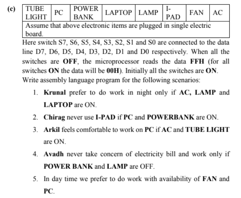
What is the size of ADD M instruction? Name the machine cycles. Draw machine cycle and T-state diagram and specify the content of address bus, data bus and control signals *RD, *WR, IO/*M and ALE signals and status signals S1 and S0 for every T states of ADD M instruction only.
(a) What are the states of the Auxiliary Carry (AC), Carry (CY), sign(S) and parity (P) flags after executing the following 8085 program?
MVI A, A9H
MVI B, 57H
ADD B
ORA A
| Instruction | CY | AC | S | Z | P |
|---|---|---|---|---|---|
| MVI A, A9H | 0 | 0 | 1 | 0 | 0 |
| MVI B, 57H | 0 | 0 | 1 | 0 | 0 |
| ADD B | 1 | 1 | 1 | 0 | 0 |
| ORA A | 1 | 0 | 1 | 0 | 1 |
The values in the table are either 0 or 1, indicating whether the flag is reset (0) or set (1) after the execution of each instruction.
(b) Explain One byte, Two byte, Three byte and write short note on different
types of instruction sets.
One byte instructions: These are the simplest instructions in the 8085 instruction set, and they occupy only one byte of memory. They usually perform simple operations like incrementing or decrementing a register or performing a logical operation on a register. Examples of one byte instructions are INR, DCR, CMA, etc.
Two byte instructions: These instructions occupy two bytes of memory, and they usually involve a register and an immediate data byte. The first byte specifies the operation to be performed, while the second byte provides the operand data. Examples of two byte instructions are MVI, LXI, STA, etc.
Three byte instructions: These instructions occupy three bytes of memory, and they are used for more complex operations like transferring data between memory locations or performing arithmetic operations on large data values. Examples of three byte instructions are MOV, ADD, SUB, etc.
There are three different types of instruction sets in 8085 microprocessor:
- Data transfer group: This group of instructions is used to transfer data between registers, memory locations, and input/output ports. Examples of instructions in this group are MOV, MVI, LDA, STA, etc.
- Arithmetic group: This group of instructions is used to perform arithmetic and logical operations on data. Examples of instructions in this group are ADD, SUB, INR, DCR, CMA, etc.
- Control transfer group: This group of instructions is used to change the sequence of execution of instructions based on certain conditions. Examples of instructions in this group are JMP, JC, JZ, CALL, RET, etc.
(c) Specify the addressing mode, required Machine cycles, T-States and function for following instructions : 1. MVI M, 45H 2. RAL LHLD 2300H
| Instruction | Addressing Mode | Machine Cycles | T-States | Function |
|---|---|---|---|---|
| MVI M, 45H | Direct | 3 | 10 | Load immediate data to memory |
| RAL | Implied | 1 | 4 | Rotate accumulator left |
| LHLD 2300H | Direct | 3 | 16 | Load register pair from memory |
(a) Difference between RLC and RAL instruction.
RLC and RAL are both instructions that perform rotation operations on the contents of the accumulator in the 8085 microprocessor. However, there are some key differences between these two instructions:

- RLC rotates the accumulator contents one bit to the left, with the bit that was previously in the most significant position now becoming the least significant bit, and the carry flag being set to the value of the bit that was rotated out. RAL, on the other hand, rotates the accumulator contents one bit to the left through the carry flag, with the carry flag itself being shifted into the least significant bit, and the carry flag being set to the value of the bit that was rotated out.
- RLC is an
8-bitinstruction that takes4 clockcycles to execute, whereas RAL is also an 8-bit instruction but takes 1 additional clock cycle to execute (i.e., 5 clock cycles in total).
Here is a table summarizing the differences between RLC and RAL:
| Instruction | Operation | Carry Flag | Execution Time |
|---|---|---|---|
| RLC | Rotate accumulator contents left | Bit 7 | 4 cycles |
| RAL | Rotate accumulator contents left | Bit 0 | 5 cycles |
Note: The carry flag in both instructions is set to the value of the bit that was rotated out.
(b) Differentiate between maskable and non-maskable interrupts.
Maskable Interrupts: Maskable interrupts are those that can be disabled or enabled by software. It means that the microprocessor can be programmed to ignore a maskable interrupt. The maskable interrupts are used for low-priority interrupt requests that can be delayed or ignored without affecting the system’s operation. Examples of maskable interrupts are external interrupts, keyboard interrupts, and serial communication interrupts.
Non-Maskable Interrupts: Non-Maskable Interrupts (NMIs) are the interrupts that cannot be disabled or ignored by the microprocessor. These interrupts are designed for critical events such as power failure, memory parity errors, or system reset. The microprocessor must respond to NMIs immediately to prevent the system from crashing or losing data. The NMIs have the highest priority and can interrupt the microprocessor at any time.
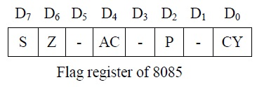
(c) What is a flag Register? Enlist and explain various types of flags.
In the 8085 microprocessor, the flag register is an 8-bit register that contains 5 flags that are set or reset based on the result of the arithmetic and logical operations performed by the processor. The 5 flags are:
Sign (S) flag: It indicates whether the result of an operation is positive or negative. If the MSB of the result is 1, the flag is set, indicating a negative result. If the MSB is 0, the flag is reset, indicating a positive result.
Zero (Z) flag: It indicates whether the result of an operation is zero or not. If the result is zero, the flag is set, else it is reset.
Auxiliary Carry (AC) flag: It indicates whether a carry occurred from bit 3 to bit 4 during an arithmetic operation involving lower nibbles. If a carry occurred, the flag is set, else it is reset.
Parity (P) flag: It indicates whether the result of an operation has an even or odd number of 1s in its binary representation. If the result has an even number of 1s, the flag is set, else it is reset.
Carry (CY) flag: It indicates whether a carry occurred from the most significant bit during an arithmetic operation. If a carry occurred, the flag is set, else it is reset.
(a) Difference between RRC and RAR instruction.
RRC instruction rotates the contents of a register or a memory location one bit to the right. The rightmost bit is rotated into the Carry flag, and the previous value of the Carry flag is rotated into the leftmost bit. This instruction is useful in performing arithmetic and logical operations in microprocessors.
RAR instruction rotates the contents of the Accumulator register one bit to the right. The rightmost bit is rotated into the Carry flag, and the previous value of the Carry flag is rotated into the leftmost bit of the Accumulator. This instruction is commonly used in binary arithmetic and logical operations.
(b) What is vectored and non-vectored interrupts?
Vectored Interraupts
A vectored interrupt is an interrupt that has a predefined vector address associated with it. When the interrupt occurs, the microprocessor or microcontroller automatically jumps to the vector address to execute the corresponding interrupt service routine (ISR).
In other words, the interrupt vector specifies the memory location of the ISR. Vectored interrupts are faster and more efficient as the microprocessor or microcontroller does not have to search for the ISR address.
Non-Vectored Interraupts
A non-vectored interrupt does not have a predefined vector address associated with it. When the interrupt occurs, the microprocessor or microcontroller must search for the ISR address using a software routine.
Non-vectored interrupts are slower and less efficient than vectored interrupts, as they require additional processing time to find the ISR address.
(c) Describe the functions of
(1) READY PIN
(2) ALE
(3) HOLD
(4) X1 and X2
(5) SID and SOD
(6) IO/M 22.
(7) HLDA
(1) READY PIN:
- The READY pin is used to synchronize the operation of the microprocessor with slower external devices such as memories and input/output (I/O) devices.
- When the READY pin is high, it indicates that the external device is ready to accept or provide data to the microprocessor. The microprocessor will only execute an instruction when the READY pin is high. If the READY pin is low, the microprocessor will wait until it goes high before executing the next instruction.
(2) ALE (Address Latch Enable):
- The ALE signal is used to latch the address from the microprocessor onto the address bus. The address is latched by external devices such as memories and I/O devices, so they know which device the microprocessor is communicating with.
(3) HOLD:
- The HOLD pin is used by external devices to request control of the address and data buses. When a device sends a HOLD request, the microprocessor completes the current instruction and sends out a HOLD ACK (acknowledge) signal.
- The external device can then take control of the address and data buses and perform its operation. Once the operation is complete, the external device sends a HOLD RELEASE signal to relinquish control back to the microprocessor.
(4) X1 and X2:
- These are the crystal oscillator pins used to provide the clock signal to the microprocessor. A crystal oscillator circuit is connected to these pins to generate the clock signal. The clock signal is used to synchronize the operation of the microprocessor and other devices.
(5) SID and SOD:
- SID (Serial Input Data) and SOD (Serial Output Data) pins are used for serial communication. The microprocessor can communicate with external devices using serial communication protocols. The SID pin is used to input serial data to the microprocessor, while the SOD pin is used to output serial data from the microprocessor.
(6) IO/M:
- The IO/M (Input/Output or Memory) pin indicates whether the microprocessor is performing an I/O or memory operation. When the IO/M pin is low, the microprocessor is performing a memory operation. When the IO/M pin is high, the microprocessor is performing an I/O operation.
(7) HLDA (Hold Acknowledge):
- The HLDA signal is used to acknowledge a HOLD request from an external device. When a device sends a HOLD request, the microprocessor completes the current instruction and sends out a HOLD ACK signal.
- The external device can then take control of the address and data buses and perform its operation. Once the operation is complete, the external device sends a HOLD RELEASE signal to relinquish control back to the microprocessor.
(a) List features of 80386 microprocessor.
32-bit architecture:The 80386 is a 32-bit microprocessor, which means it can handle larger data sizes and address larger amounts of memory than its predecessors.Virtual memory support:The 80386 supports virtual memory, which allows a program to use more memory than is physically available by using disk storage as an extension of main memory.Protected mode:The 80386 supports protected mode, which provides a secure environment for running multiple applications simultaneously without interfering with each other.Built-in memory management unit (MMU):The 80386 has a built-in memory management unit, which allows it to map physical memory addresses to virtual addresses and manage memory access permissions.Improved instruction set:The 80386 introduced new and improved instructions, including new arithmetic and logic instructions, as well as new memory access and control instructions. These instructions improved performance and made it easier for developers to write efficient code.
(b) Draw block diagram of SUN SPARC architecture.
Refer this : https://www.euroben.nl/reports/web13/sparc.php
(c) Explain the internal Block diagram of 8259A.

Interrupt Inputs: The 8259 chip has eight interrupt inputs (INT0 to INT7) that can be connected to various sources in the computer system. Each of these inputs can be enabled or disabled using control registers.
Interrupt Request Register (IRR): The IRR is an 8-bit register that stores the interrupt requests from the interrupt inputs. Each bit in the register corresponds to an interrupt input.
Interrupt In-Service Register (ISR): The ISR is an 8-bit register that stores the interrupts that are currently being serviced by the microprocessor. Each bit in the register corresponds to an interrupt input.
Interrupt Mask Register (IMR): The IMR is an 8-bit register that is used to enable or disable interrupts from the interrupt inputs. Each bit in the register corresponds to an interrupt input.
Priority Resolver: The priority resolver is a logic circuit that determines the highest priority interrupt request that needs to be serviced by the microprocessor. It selects the interrupt with the highest priority and sends its interrupt number to the microprocessor.
Control Logic: The control logic includes various control registers and control signals that are used to manage the interrupts. It includes the Initialization Command Word (ICW) register, the Interrupt Mask Command (IMC) register, and the End of Interrupt (EOI) signal.
Cascade Buffer: The 8259 chip can be cascaded with other 8259 chips to handle more than eight interrupts. The cascade buffer is a set of pins that allow multiple 8259 chips to be connected together.
(a) List features of 80486 microprocessor.
- 32-bit architecture: The 80486 is a 32-bit microprocessor, which means it can handle larger data sizes and address larger amounts of memory than its predecessors.
- Integrated Floating-Point Unit (FPU): The 80486 includes an integrated FPU, which allows it to perform floating-point calculations much faster than its predecessors.
- Improved cache performance: The 80486 features an improved cache memory system that can store more data and instructions than its predecessors. This helps to reduce the time it takes to access frequently used data and instructions.
- Pipelining: The 80486 features a five-stage pipeline, which allows it to execute multiple instructions simultaneously and improve overall performance.
- Support for multiple operating modes: The 80486 supports multiple operating modes, including real mode, protected mode, and virtual mode. This provides greater flexibility for software developers and allows them to write more efficient code.
(b) Draw logical block diagram of ARM 7 architecture.

(c) Explain the internal Block diagram of 8255A.

Control Logic: The control logic includes various control registers and control signals that are used to configure and manage the operation of the chip. It includes the Control Word Register (CWR), the Mode Set Register (MSR), and various control signals such as RD, WR, and CS.
Data Bus Buffer: The data bus buffer is used to buffer the data between the chip and the CPU.
Port A: Port A is an 8-bit bidirectional I/O port that can be configured as input or output.
Port B: Port B is an 8-bit bidirectional I/O port that can be configured as input or output. It also includes two control signals, STB (Strobe) and CLK (Clock), that are used for handshake operations.
Port C: Port C is an 8-bit port that can be divided into two parts, Port C Lower (PC0-PC3) and Port C Upper (PC4-PC7). The Lower part can be configured as input or output, while the Upper part can be used for various modes of operation such as mode 0, mode 1, and mode 2.
Mode Set Register: The Mode Set Register (MSR) is used to configure the operation of the chip. It includes various control bits that are used to select the mode of operation for each port.
Control Word Register: The Control Word Register (CWR) is used to configure the operation of the chip. It includes various control bits that are used to select the mode of operation for each port, and to enable or disable the various features of the chip.
Read More : ETC GTU Paper Solution Winter 2021
Read More : Indian Constitution GTU Paper Solution Winter 2021
“Do you have the answer to any of the questions provided on our website? If so, please let us know by providing the question number and your answer in the space provided below. We appreciate your contributions to helping other students succeed.